IEEE ICRA · 2019 · an animated walkthrough

UAV/UGV Autonomous Cooperation: UAV assists UGV to climb a cliff by attaching a tether

The paper in 105 seconds · narrated · sound on
Transcript

A drone winds a cable around a pole on a clifftop, and its partner winches itself up the cliff. That winch can climb a vertical wall, or a flight of stairs. But how do two robots do this all by themselves?

Robots are sent into disaster sites, rough fields, even other planets, and they keep hitting the same wall: a drop they can’t drive up. A ground robot carries heavy tools but can’t climb, or see over the edge. A drone flies over anything, but carries little, and tires fast.

A winch, a motor that reels in cable, can pull a robot up, like a climber on a rope. But in earlier systems, a person or a second rover had to fix it at the top first.

This paper’s idea: the drone is the friend at the top. It flies the cable over, winds it around a pole, and lands. Then the ground robot reels itself up.

The drone flies ahead and maps the ground in 3-D. The ground robot plans its route on that map, and when every route costs too much, it knows: cliff. To find an anchor, the drone looks for height that’s concentrated, like a pole, not spread out, like an edge. The drone circles the pole once, then half a turn more: one of the two best stopping points in their hook tests.

In the lab, the whole mission ran by itself, and both robots ended up on top. As far as the authors know, it’s the first time a drone has fixed the anchor for a ground robot, so no one has to prepare the way. The catch: a slack cable kept tangling the robot, so keeping it tight comes next.

Footage (opening and the “whole mission” shot): the authors’ ICRA 2019 video, “UAV/UGV Autonomous Cooperation” (AILAB UTokyo YouTube channel), by Takahiro Miki, Petr Khrapchenkov and Koichi Hori, The University of Tokyo. Voice: Kokoro TTS (synthetic). Music and sound effects: synthesized for this video.

The story in plain words

A drone flies a cable up a cliff and winds it around a pole, so the ground robot tied to the other end can reel itself up to places it could never drive to.

  1. Why this matters

    Robots are sent into disaster areas, rough outdoor fields and, one day, onto other planets. The ground robot is the one that does the real work there: it carries heavy sensors, strong computers and robot arms. But the ground often turns into a steep drop, and everything above it is out of reach.

  2. What makes it hard

    Each robot type is good at half the job. A ground robot has the battery and payload but can’t climb and can’t see far. A drone flies over anything and sees from above, but carries little and runs out of battery fast. Picture a hiker with a heavy pack at the foot of a rock wall: strong, but stuck.

  3. What people did before

    Drone-and-ground-robot teams already existed, but the drone was only a flying camera. Robots with a winch (a motor that reels in cable) can pull themselves up steep slopes and crater walls, but a person or a second rover had to fix the cable at the top first. So they only reach places someone could already get to.

  4. What this paper does

    The drone becomes the friend at the top of the wall. The two robots are joined by a cable. The drone maps the way, flies the free end over the cliff, winds it around a pole with a small grappling hook, and lands. Then the ground robot reels the cable in and pulls itself up. Everything runs on its own: mapping, route planning, spotting the cliff, finding the pole, winding and landing.

  5. What they showed

    Each part worked in a test: the drone flew 2 m past a board a person held in its way and landed where the ground robot told it to; the winch pulled the robot up a vertical wall and up stairs; hook tests showed which way to leave the pole. Then the whole mission ran by itself in an indoor field with an obstacle, a steep slope and a pole, and both robots ended up on top.

  6. Why it’s a step forward

    As far as the authors know, it is the first system where a drone fixes the anchor that a ground robot then climbs, so no one has to prepare the way. The honest catch: with no way to keep the cable tight, the slack cable tangled the robot many times, and getting the hook back off is still unsolved.

Words used below
UAV / UGV
unmanned aerial vehicle (drone) / unmanned ground vehicle (ground robot)
tether
the cable joining the two robots
winch
a motor on the ground robot that reels the tether in
anchor
what the tether is fixed to at the top, here a pole
voxel map
a 3-D map made of small cubes, from the drone’s depth camera
traversability
a 0–1 score for how easy ground is to drive over
1 / 8
UAV (drone) UGV (ground robot) tether / anchor
Scene 1

Read the full section with the paper’s figures ↓

The paper, section by section

Everything the animation skips

Each section matches one scene above. Press “Watch scene” to jump back to its animation; click any figure to enlarge it. Figures are from the paper; the text is a plain-language walkthrough.

Scene 1

Why it matters

In short: robots that explore dangerous places keep getting stopped by steep drops, and what lies above stays unexplored.

The paper opens with the places exploration robots must work in: disaster areas, rough outdoor fields and planet surfaces. In all of them the ground is broken, steep and unknown, and no one can go ahead to prepare a route.

The robot you want there is a ground robot (a UGV, an unmanned ground vehicle). It has a large battery and can carry heavy equipment: sensors, strong computers, even robot arms that can pick things up. But a ground robot can only go where its tracks can take it. A drop taller than the robot, like a collapsed floor, a steep bank or a crater wall, ends the mission.

The player scene shows these settings as simple illustrations. The paper itself tests the idea in an indoor lab field (scene 4).

Scene 2

Two robots, opposite weaknesses

In short: a drone can see and reach the top but can’t carry much; a ground robot can carry a lot but can’t get up. Earlier teams only used the drone as a camera.

The paper sets up a simple trade-off:

  • A drone (UAV, an unmanned aerial vehicle) is easy to get anywhere. It flies over obstacles, rough ground and steep slopes, and sees a wide area from above. But its payload and battery are small, so heavy equipment and complex handling are out of reach.
  • A ground robot has a bigger battery and payload, but its sensors don’t see far, and it is poor at crossing rough terrain and climbing.

What people did before, and where it stops

Drone as a flying camera. Many air–ground teams fix the ground robot’s short sight: the drone scans a wider area so the ground robot can find its way. One team, for example, mapped an earthquake-damaged building with a drone that rode on the ground robot until the way was blocked. Tether-powered drones fix the drone’s battery problem by sending power up a cable, and some systems even connect a drone and a ground robot with a cable. In all of them, though, the drone only senses.

A winch and a cable. For climbing, a winch (a motor that reels in cable) works, like a climber being hauled up on a rope. Off-road cars winch themselves up very steep slopes; two-wheeled tethered rovers have explored steep crater walls with the help of a “mother” vehicle; one tethered rover built 3-D maps of steep terrain. The catch: the tether must be fixed at the top beforehand, by a parent rover or a person. So the robot can only reach places someone could already get to, plus what hangs below them. One exception fires a grappling hook upward, but it can’t get over a cliff or aim at an anchor it can’t see from below.

Scene 3

The drone places the anchor

In short: the drone carries the cable over the cliff and winds it around a pole; the ground robot then reels itself up. The drone is both the scout and the one who fixes the rope.

The proposal: connect the two robots with a tether and let the UAV fix its end on top of the cliff. The drone is then two things at once: a flying sensor that maps the terrain for the ground robot, and the device that attaches the anchor where the ground robot can’t go. The UGV carries a winch strong enough to lift its own mass and winds the tether to climb.

The authors say that, to their knowledge, this is the first system that uses a UAV to attach a tether the UGV then uses to extend where it can reach. For it to work on its own, the drone must detect an anchor point and attach the tether automatically; the drone also needs state estimation, trajectory following, obstacle avoidance and 3-D mapping; and the ground robot must plan paths from the drone’s map.

Paper Fig. 1. The concept. The drone scans the ground (coloured cone) and carries the tether over the cliff to a tree; the tracked robot below winds it in.

What the paper contributes

  1. A cooperative system that navigates an unknown environment together, uses the drone to attach a tether where the ground robot can’t reach, and lets the ground robot climb steep terrain with that tether.
  2. A comparison of ways to attach a tether (scene 7).
  3. A framework for autonomous joint navigation, cliff detection and tether attachment.
Scene 4

One autonomous mission

In short: in a lab field with an obstacle, a steep slope and a pole, the two robots did the whole job by themselves, one step after another.

The test mission, in the paper’s words, runs like this. Both robots start together and head for a goal. Until they reach a cliff, the UAV flies ahead of the UGV and builds a voxel map (a 3-D map made of small cubes); the UGV plans a path on that map that avoids obstacles and rough ground, and follows the drone. Once a cliff is detected, the UAV flies above it and searches for an anchoring point. When it finds one, it flies around it to attach the tether, then lands autonomously in a safe area. Finally the UGV winds the tether and climbs. The mission ends when the cliff is climbed.

The field was built indoors: an obstacle in front of the UGV, a steep slope in the middle, and a pole on top of the slope as the intended anchor. The two robots share their positions and maps over Wi-Fi through ROS (the Robot Operating System, common robot software).

Fig. 3a. The indoor field: start positions, obstacle, cliff, goal and the pole.
Fig. 3b. The voxel map after the run; red is the drone’s path, blue the ground robot’s.
Fig. 3c. Top view, coloured by traversability.

The 3-D scene follows this layout. Its timing and paths are illustrative, not replayed from logs. In the real run, the UAV’s motor stop and the winch switch were triggered by hand for safety.

Method

The drone: on-board localization, mapping, planning

In short: the drone works out where it is, maps what it sees and plans around obstacles, all with its own small computer, and shares the map with the ground robot.

Hardware. A custom-made quadrotor with an NVIDIA Jetson TX2 for fully on-board localization, mapping and navigation, plus a custom flight controller for attitude control and sensor interfaces. Sensors: a global-shutter monocular fisheye camera, a time-of-flight (ToF) depth camera, a laser for height, and the flight controller’s IMU. The TX2 and the flight controller talk over serial, with telemetry and commands both at 100 Hz.

SensorUsed forRate
Fisheye cameravisual-inertial odometry (ROVIO)20 Hz
ToF camerapoint cloud → Octomap voxels5 Hz
Laserheight, to cancel VIO height drift100 Hz
IMUattitude control; fused in the EKF100 Hz

What this means: the slow sensors (camera, depth) give position and shape; the fast ones (laser, IMU) fill in between, so the controller gets odometry quickly enough to fly close to a pole.

Software. The drone has no GPS indoors, so it must work out its own position from what it sees. It uses visual-inertial odometry (VIO: tracking its motion from camera images plus the motion sensor, the IMU), following an earlier drone framework. The VIO library ROVIO was chosen because it needs no start-up motion and is light to compute. A Kalman filter fuses the VIO pose with the laser height, estimates both the VIO and the laser bias, and throws out laser outliers by Mahalanobis distance. An extended Kalman filter (EKF, a standard way to blend noisy sensors) then fuses that with the IMU for fast position updates.

For obstacles, the Octomap library builds a voxel map from the ToF camera’s depth points, and a motion-primitive planner (a customized MRSL Motion Primitive Library ROS package) computes an obstacle-avoiding reference trajectory at 5 Hz, which matters because attaching the tether means flying close to structures. A linear MPC (model predictive control: repeatedly plan the next moments of motion with a simple model, apply the first step), using a measured model of how the drone tilts, turns the trajectory into roll, pitch, yaw-rate and thrust commands; the flight controller’s PID loop does the rest.

Animated. The drone’s on-board pipeline builds up: position from camera, laser and IMU, then the voxel map and planner, then the controller. The map goes to the ground robot. Dot spacing hints at the sensor rates.
Paper Fig. 2. The whole software framework on ROS: UAV blocks on the left (Jetson TX2), UGV blocks on the right (UP Core), linked over Wi-Fi.
Paper Fig. 4a. The drone: Jetson TX2, flight controller, pico flexx ToF camera, height laser and fisheye camera.

Test: fly, dodge, land

The drone took off to 1 m, flew towards a goal 2 m ahead, and had to dodge an obstacle a person held up on the way. At the end, the grid map was used to pick a safe landing spot, computed on the UGV, and the drone landed there (the final motor stop was done by hand for safety). The paper reports that localization and control were good enough for a fully autonomous mission.

Animated. Watch the dashed plan snap around the board as soon as its voxels appear. The planner re-plans at 5 Hz. Motion is illustrative.
Fig. 5a. The setting: a person holds up a board.
Fig. 5b. The planned trajectory around the obstacle.
Fig. 5c. The path actually flown.
Real run. The obstacle test from the authors’ video: a person holds a board in the drone’s path, and the drone flies around it and keeps going. The coloured blocks at the bottom left are the authors’ overlay of the drone’s voxel map. Cropped to hide an on-screen state-machine panel. Footage: Takahiro Miki, Petr Khrapchenkov and Koichi Hori, The University of Tokyo (the authors’ ICRA 2019 video).
Scene 5

The ground robot: map, path, cliff test

In short: the ground robot turns the drone’s map into a “how easy is it to drive here” score, plans the cheapest route, and concludes “cliff” when every route is too expensive.

Hardware. A custom robot on a commercial tracked (caterpillar) platform with an UP Core computer, an IMU, per-motor PID control with encoders, and a custom winch. The winch motor uses a simple sensorless relay switch to get high power output. The computer exchanges commands and odometry with the motor controller at 100 Hz.

Paper Fig. 4b. The ground robot: winching motor, reduction belt, winching spool and hook on a tracked base.

Software. The UGV keeps track of its position by dead reckoning: adding up wheel-track motion and IMU readings. It receives voxels from the UAV, converts them to a grid map, and runs path planning and cliff detection on it; a standard path-following method (Pure Pursuit: steer toward a point a little way ahead on the path) drives it.

From voxels to traversability

The ToF depth data are noisy, so the grid map is filtered in several passes: inpainting of holes, slope and roughness, then traversability:

traversability = ½ · (1 − slope / 0.6) + ½ · (1 − roughness / 0.1)  // slope in rad, roughness in m

A minimum filter with a 30 cm radius then spreads low traversability to the neighbouring cells, so the robot keeps its distance from bad spots.

Animated. The two halves of the formula: tilt the patch and the slope term drops; roughen it and the roughness term drops. The paper does not say how values outside 0–1 are handled; the animation clamps them.

Path cost and cliff detection

A* (a classic shortest-path search) finds the cheapest route across the 2-D grid. Each cell costs

cost_i = W_T / (T_i + ε_T) + W_E · E_i   (W_NaN if the cell is unknown)  // T: traversability, E: elevation

The planner doesn’t model the tether or the robots’ motion. Cliff detection reuses it: if a cheap path to the goal exists, there is no cliff. If even the best path costs more than a threshold, the way is blocked. To avoid a false alarm when the goal itself sits on an obstacle, the goal is moved around within a range and the lowest-cost variant is kept. If that still exceeds the threshold, there is an unavoidable cliff, and that lowest-cost goal is handed to the state machine for the next manoeuvre.

Animated. Five goals near the original one; every path has to cross the red cliff band, so all of them stay over the threshold. Weights, grid and threshold are illustrative: the paper gives the formulas, not the values.

Landing spot. Around the drone’s current position, the UGV looks for cells with a defined value, a small elevation difference, low slope and high traversability, and hands such a spot to the state machine.

Scene 6

Finding an anchor: peakness

In short: to find something to wind the cable around, the drone looks for spots where the height is concentrated in one point, like a pole, rather than spread along a line, like an edge.

A good anchor stands some height above the surface, is not in a cluttered area, and sticks up clearly: a tree trunk, a stump, an outcropping rock, a pole. The drone searches the UGV’s grid map around its current position with a filter on the elevation layer that scores peakness.

For a candidate cell c, take the valid neighbours 𝒩 within a radius, and let h(p) be each neighbour’s height above the lowest cell in 𝒩. Weighting offsets by that height gives a covariance:

σ_x² = (1/N) Σ h(p)(x − x_c)²   σ_y² = (1/N) Σ h(p)(y − y_c)²   σ_xy² = (1/N) Σ h(p)(x − x_c)(y − y_c)
Σ = [σ_x² σ_xy²; σ_xy² σ_y²]  →  σ_l² = larger eigenvalue of Σ  →  peakness = 1 / σ_l²

Above a threshold, the cell is an anchor. The filter only runs on cells that are the highest within their radius. The key choice is the larger eigenvalue: a pole keeps both small, but an edge spreads height along one direction, so the smaller eigenvalue or the mean would also mark edges as anchors.

Animated. The pole’s ellipse stays a dot; the ridge’s ellipse stretches along it. Only the larger-eigenvalue score tells them apart. The numbers come from these made-up grids, not from the paper.
Scene 7

Attaching the tether

In short: of six ways to fix a cable, the paper picks a hook plus winding. The drone circles the pole once and then half a turn more, because that stopping point caught best in tests.

This is the most unusual part of the system. The paper weighs six ways to fix a tether to the environment:

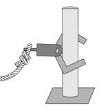
  1. Grappling hook: light and simple, but it is hard to find a spot to hook, and the hook can come loose.
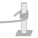
  2. Winding the tether a few turns around a pole, held by friction: no special device, but the drone must find a pole and fly the right path. A rope bridge was once built this way, but with pre-computed trajectories and motion capture.
  3. Grasping device: the drone itself becomes the anchor and can let go easily, but it can’t grip large structures and may get too heavy for the torque a large UGV needs.
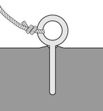
  4. Peg driven into soil: works almost anywhere there is soil, but the insertion mechanism gets complex.
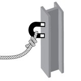
  5. Magnet launched at the target: limited to magnetic surfaces.
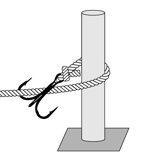
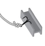
  6. Hybrid hook + winding: the drone winds a grappling hook around the structure, which raises the chance of a successful anchor compared with 1 or 2 alone.
Criterion hook iconHookwinding iconWindinggrasping iconGrasppeg iconPegmagnet iconMagnethook plus winding iconHook + wind
device simplicity★★★★★★★★★★★★★★★★★★
control simplicity★★★★★★★★★★★★★★★★★★
lightness★★★★★★★★★★★★★★★★★★
unhooking capability★★★★★★★★★★★★★★★★★★
strength★★★★★★★★★★★★★★★★★★

What this means: the hybrid ties for best on simplicity and lightness and is the only one with full marks for strength. Its weak spot, shared with hook and winding, is getting the tether back off, which the paper leaves for future work.

How far to go around

After one full revolution around the pole, the drone keeps going by a revolution angle before leaving. To choose it, the authors placed the hook by hand every 20° and pulled it with the winch on a smooth floor. Only cases where the hook caught the tether counted as success; catching on the surroundings counted as failure. The most successful angles were near 0° or 180°. The mission uses 180°: it raises the chance of hooking onto some structure, and it keeps clear of the UGV after it climbs.

Animated. One full turn, then 180° more: the tether end ends up on the far side of the pole from the UGV.
Paper Fig. 7a. How the revolution angle is measured, after one full turn.
Paper Fig. 7b. Success rate per revolution angle (radial axis 0–1). The paper states the conclusion in words only; we don’t read exact values off the chart.
Scene 8

Results

In short: every part worked in a test, and the full mission succeeded once in the lab. The paper reports these as outcomes, without success rates.

Each component was tested first, then the whole mission. The paper reports all outcomes in words; there are no success rates or trial counts for the navigation or the mission.

ExperimentWhat was doneOutcome (paper)
UAV navigation (Fig. 5)Take off to 1 m, fly 2 m, dodge a hand-held obstacle, land on a spot computed on the UGVTook off, avoided the obstacle, landed on the spot. Motor stop by hand.
UGV climbing (Fig. 6)Tether fixed at the top by hand, winch wound, manual controlClimbed a vertical wall and stairs.
Tether attachment (Fig. 7)Hook placed every 20° after one turn, pulled by the winchBest near 0° or 180°; 180° chosen.
Whole mission (Figs. 3, 8)Autonomous cooperative navigation, cliff and pole detection, tether winding, landing, climbBoth robots finished on top of the cliff. UAV motor stop and winch switch by hand.

What this means: every step of the chain worked at least once in the lab, which shows the idea is feasible. How reliably it works was not measured.

Paper Fig. 6a. Winching up a vertical wall.
Paper Fig. 6b. Winching up stairs.
Real run. The climbing test: with the tether fixed at the top by hand, the winch pulls the ground robot up a staircase (paper Fig. 6b, manual control). Footage: Takahiro Miki, Petr Khrapchenkov and Koichi Hori, The University of Tokyo (the authors’ ICRA 2019 video).
Paper Fig. 8a. The drone flying around the pole to attach the tether.
Paper Fig. 8b. The ground robot climbing the cliff on the attached tether.
Real run. The end of the autonomous mission: the ground robot winches itself over the edge of the steep slope and drives onto the top. Cropped to hide the authors’ picture-in-picture and state-machine overlays. Footage: Takahiro Miki, Petr Khrapchenkov and Koichi Hori, The University of Tokyo (the authors’ ICRA 2019 video).
Limits

What didn’t work, and what’s next

In short: the biggest problem was a slack cable tangling the ground robot; keeping the cable tight is the key next step.

Tether slack. This was the main lesson. With no tension sensor there was no tension control, so the tether had to be let out from the start. Lying on the ground, it got tangled in the UGV many times as the robot drove towards it, and the experiment had to be stopped. Without the tether, the navigation succeeded “with a high probability”.

Animated. The failure mode: the tether is paid out ahead of time, lies on the floor, and the UGV drives into it. Motion is illustrative.
  • Safety steps were manual: the UAV’s motor stop and the winch switch in the mission, and the final motor stop in the flight test.
  • One indoor field, with a pole placed as the anchor. Natural anchors (trees, rocks) are discussed but not tested.
  • No reliability numbers. Outcomes are reported as successes, without trial counts.
  • Unhooking the tether after the climb is not solved.
  • The path planner ignores the tether and the robots’ motion models.

Future work named in the paper: smarter tether tension control (called crucial), tether-aware planning, power and communication over the tether, collaborative mapping and localization, and tether unhooking.